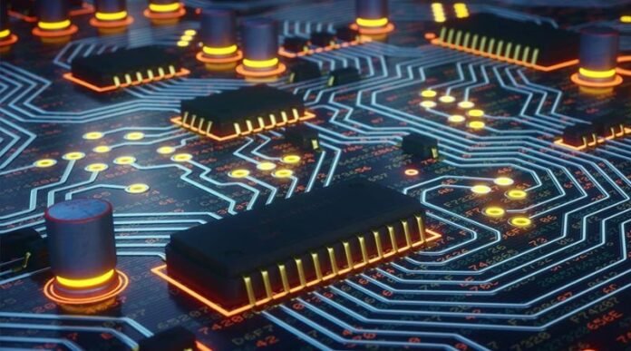
High speed and high density interconnect (HDI) PCB is a form of printed circuit board that was designed for high-frequency and high-density circuits. HDI boards are made using copper foil, which makes them more durable than other types of boards such as FR4 or FR2. However, the price tag on HDI boards is higher than those made from FR4 because they require more expensive manufacturing processes.
What is HDI PCB?
- What is HDI PCB?
HDI PCBs, or high density interconnect boards, are a combination of two materials—a core material and a copper clad laminate. The core material typically consists of FR-4 epoxy glass. The copper clad laminate consists of multiple layers (typically three) that are separated by an insulating layer. The outermost layer of this stack would be aluminum foil as it is used for shielding purposes in some applications.
The Advantages of HDI PCB.
High density:
The HDI technology is a revolutionary approach to saving space in your PCB. The increased thickness of the boards makes them suitable for high-density interconnects, which improves signal integrity and reduces crosstalk between traces on a given layer.
HIGH PERFORMANCE:
High performance can be achieved through reduced signal propagation delays and improved reliability due to less solder joints needed for assembly. High-frequency signals can be routed over these dense paths without significant signal degradation or loss of functionality. This means that your device will have better performance than its predecessors because it has higher bandwidth capabilities and lower latency times than previous PCBs manufactured using traditional methods like single-sided or multi-layer boards with ball grid arrays (BGA) packages soldered onto them
Comparison of PCB Materials for High Speed and HDI PCB Boards.
PCB materials differ in many respects, but the main differences between the various types of board materials are the following:
- Rigidity. Rigid boards are more durable, stronger and stiffer than flexible circuits or HDI boards. They can withstand greater mechanical stress without being damaged, so they often have a longer lifespan and require less maintenance than other kinds of PCBs. However, this also means that they’re heavier and bulkier to transport.
- Cost. Rigid boards tend to be more expensive than flexible circuits or HDI boards since they cost more money to produceand because manufacturers need fewer materials when making them (the less material that’s needed, the lower the price).
Comparison of Flexible Circuits and Rigid Boards.
Rigid boards are used in high frequency applications, and flexible circuits are used in low-frequency applications. The price of both rigid boards and flexible circuits is similar, but it’s more expensive to use a flexible circuit board than a rigid board.
Flexible circuit boards are difficult to manufacture compared with rigid boards because they require special equipment and processes that aren’t required for the production of rigid PCBs. Flexible PCBs also require an extra layer during assembly (i.e., insulation). This extra layer adds thickness and can cause problems during manufacturing or repair by adding additional cost and complexity to the process, as well as lengthening lead times due to increased cycle time per unit produced.
High Speed Rigid Boards vs. High Speed Flex Circuits?
High speed flex circuits are more expensive to manufacture and assemble than high-speed rigid boards, but they have several advantages over rigid boards:
- They’re smaller and lighter than rigid boards. This is particularly important in applications where size, weight, or both matter. For example, a miniaturized version of a product may require the use of flexible circuitry rather than a larger PCB board that’s been redesigned for miniaturization. The flexibility also helps in situations where space is limited or irregularly shaped—for example when laying out part interconnections on curved surfaces such as those found inside automobiles and airplanes.
- The low profile also means less material is used during manufacturing which reduces costs even further compared with using traditional high-speed PCBs (or other types).
- Finally, because these designs are smaller it’s easier for technicians who work on them to access areas that were previously difficult to reach without making changes or modifications first (i
Which type of board is right for you?
When it comes to selecting the right board type for your application, there are a few things you should consider. For high speed designs, like those used in HDI and MEMS applications, rigid boards tend to be superior. They offer lower capacitance and better signal quality than their flexible counterparts. However, it’s important to note that this is only true for high speeds; if you’re looking for a board that operates at low frequencies (such as an audio amplifier or motor controller) hvlp pcb, then flexible circuits may be your best bet. Because of their greater manufacturing difficulty and higher price point compared with flex circuits, rigid boards are often considered “premium” products.
Conclusion
In the end, it’s clear that rigid boards and flexible circuits have their own strengths and weaknesses. Each type of material is better suited for certain applications and uses than others. As a result, choosing which type of PCB you need can often come down to the specific application at hand and what kind of performance you expect from your board. If you’re still unsure about which material would work best for your needs or if you want more information on other types of electronics products like custom enclosures or even connectors such as USB connectors , contact us today!


